Service Manual (KLZ1000C) — page 558 of 762
Electrical System › Meter Unit Inspection
Text on this page
16-76 ELECTRICAL SYSTEM
Meter, Gauge, Indicator Unit
Meter Unit Inspection
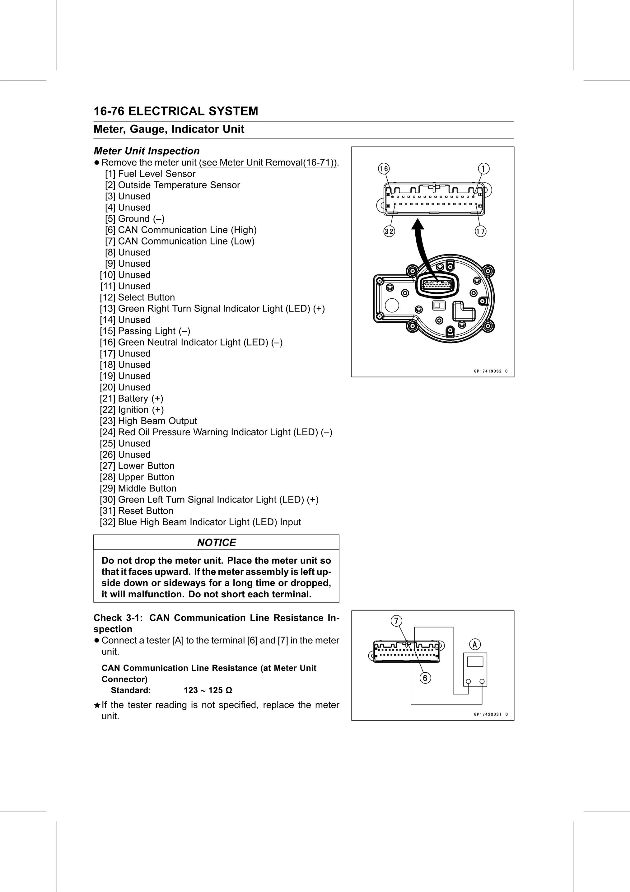
• Remove the meter unit (see Meter Unit Removal(16-71)).
[1] Fuel Level Sensor
[2] Outside Temperature Sensor
[3] Unused
[4] Unused
[5] Ground (–)
[6] CAN Communication Line (High)
[7] CAN Communication Line (Low)
[8] Unused
[9] Unused
[10] Unused
[11] Unused
[12] Select Button
[13] Green Right Turn Signal Indicator Light (LED) (+)
[14] Unused
[15] Passing Light (–)
[16] Green Neutral Indicator Light (LED) (–)
[17] Unused
[18] Unused
[19] Unused
[20] Unused
[21] Battery (+)
[22] Ignition (+)
[23] High Beam Output
[24] Red Oil Pressure Warning Indicator Light (LED) (–)
[25] Unused
[26] Unused
[27] Lower Button
[28] Upper Button
[29] Middle Button
[30] Green Left Turn Signal Indicator Light (LED) (+)
[31] Reset Button
[32] Blue High Beam Indicator Light (LED) Input
NOTICE
Do not drop the meter unit. Place the meter unit so
that it faces upward. If the meter assembly is left up-
side down or sideways for a long time or dropped,
it will malfunction. Do not short each terminal.
Check 3-1: CAN Communication Line Resistance In-
spection
•Connect a tester [A] to the terminal [6] and [7] in the meter
unit.
CAN Communication Line Resistance (at Meter Unit
Connector)
Standard: 123 125 Ω
If the tester reading is not specified, replace the meter
unit.