Service Manual (KLZ1000C) — page 622 of 762
Self-Diagnosis System › Throttle Position Sensor Output Voltage Inspection
Text on this page
17-20 SELF-DIAGNOSIS SYSTEM
Throttle Position Sensor (Service Code 11) (DTC P0120, P0121, P0122, P0220,
P0223)
If the reading is out of the standard, remove the ECU and
check the wiring for continuity between harness connec-
tors.
○Disconnect the ECU and sensor connectors.
Wiring Continuity Inspection
ECU Connector [A] ←→
Throttle Position Sensor Connector [B]
ECU Terminal 75 [C] ←→ Sensor Terminal [D]
ECU Terminal 130 [E] ←→ Sensor Terminal [F]
If the wiring is good, check the ECU for its ground and
power supply (see ECU Power Supply Inspection(3-39)).
If the ground and power supply are good, replace the
ECU.
Throttle Position Sensor Output Voltage
Inspection
• Measure the output voltage at the throttle position sensor
in the same way as input voltage inspection, note the fol-
lowing.
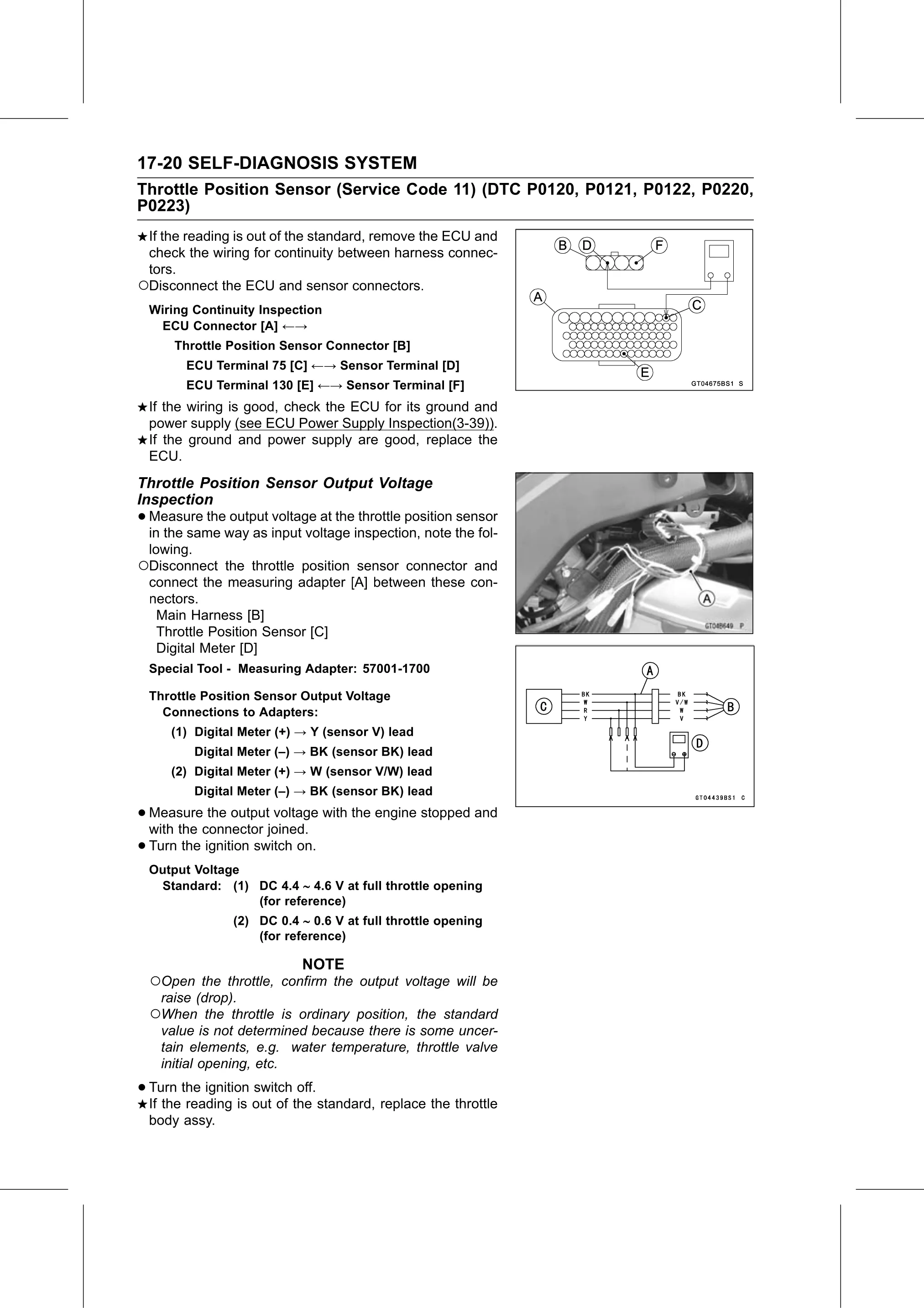
○Disconnect the throttle position sensor connector and
connect the measuring adapter [A] between these con-
nectors.
Main Harness [B]
Throttle Position Sensor [C]
Digital Meter [D]
Special Tool - Measuring Adapter: 57001-1700
Throttle Position Sensor Output Voltage
Connections to Adapters:
(1) Digital Meter (+) → Y (sensor V) lead
Digital Meter (–) → BK (sensor BK) lead
(2) Digital Meter (+) → W (sensor V/W) lead
Digital Meter (–) → BK (sensor BK) lead
• Measure the output voltage with the engine stopped and
with the connector joined.
• Turn the ignition switch on.
Output Voltage
Standard: (1) DC 4.4 4.6 V at full throttle opening
(for reference)
(2) DC 0.4 0.6 V at full throttle opening
(for reference)
NOTE
○Open the throttle, confirm the output voltage will be
raise (drop).
○When the throttle is ordinary position, the standard
value is not determined because there is some uncer-
tain elements, e.g. water temperature, throttle valve
initial opening, etc.
• Turn the ignition switch off.
If the reading is out of the standard, replace the throttle
body assy.