Service Manual (KLZ1000C) — page 642 of 762
Self-Diagnosis System › Accelerator Position Sensor Circuit
Text on this page
17-40 SELF-DIAGNOSIS SYSTEM
Accelerator Position Sensor (Service Code 18) (DTC P2120, P2121, P2123,
P2125, P2128)
 If the reading is within the standard, remove the ECU and
 check the wiring for continuity between harness connec-
 tors.
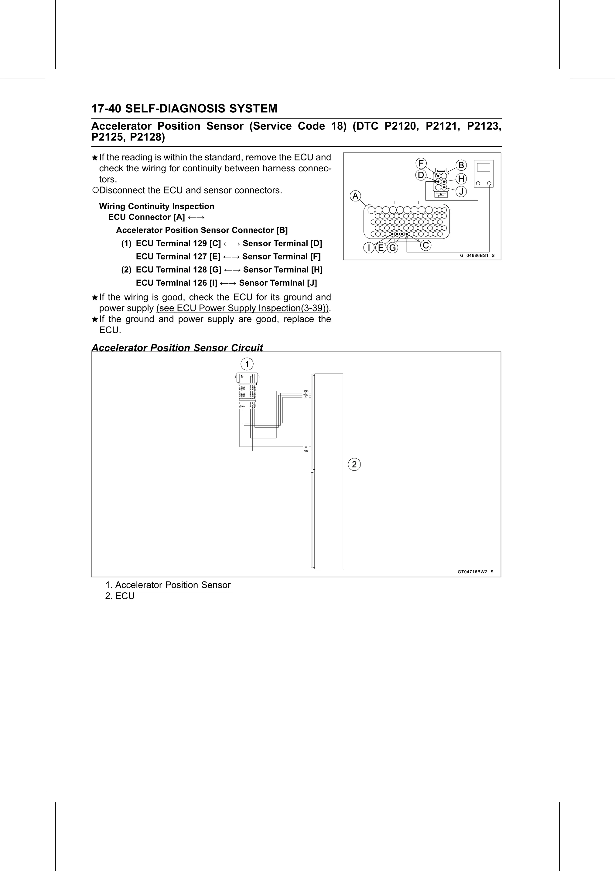
○Disconnect the ECU and sensor connectors.
 Wiring Continuity Inspection
  ECU Connector [A] ←→
      Accelerator Position Sensor Connector [B]
       (1) ECU Terminal 129 [C] ←→ Sensor Terminal [D]
          ECU Terminal 127 [E] ←→ Sensor Terminal [F]
       (2) ECU Terminal 128 [G] ←→ Sensor Terminal [H]
          ECU Terminal 126 [I] ←→ Sensor Terminal [J]
 If the wiring is good, check the ECU for its ground and
 power supply (see ECU Power Supply Inspection(3-39)).
 If the ground and power supply are good, replace the
 ECU.
Accelerator Position Sensor Circuit

   1. Accelerator Position Sensor
   2. ECU