Service Manual (KLZ1000C) — page 654 of 762
Self-Diagnosis System › Vehicle-down Sensor Output Voltage Inspection
Text on this page
17-52 SELF-DIAGNOSIS SYSTEM
Vehicle-down Sensor (Service Code 31) (DTC C0064)
 If the reading is out of the standard, remove the ECU and
 check the wiring for continuity between harness connec-
 tors.
○Disconnect the ECU and sensor connectors.
    Wiring Continuity Inspection
     ECU Connector [A] ←→
        Vehicle-down Sensor Connector [B]
          ECU Terminal 22 [C] ←→ Sensor Terminal [D]
          ECU Terminal 16 [E] ←→ Sensor Terminal [F]
    If the wiring is good, check the ECU for its ground and
    power supply (see ECU Power Supply Inspection(3-39)).
    If the ground and power supply are good, replace the
    ECU.
Vehicle-down Sensor Output Voltage Inspection
• Remove:
   Vehicle-down Sensor (see Vehicle-down Sensor Re-
     moval(17-50))
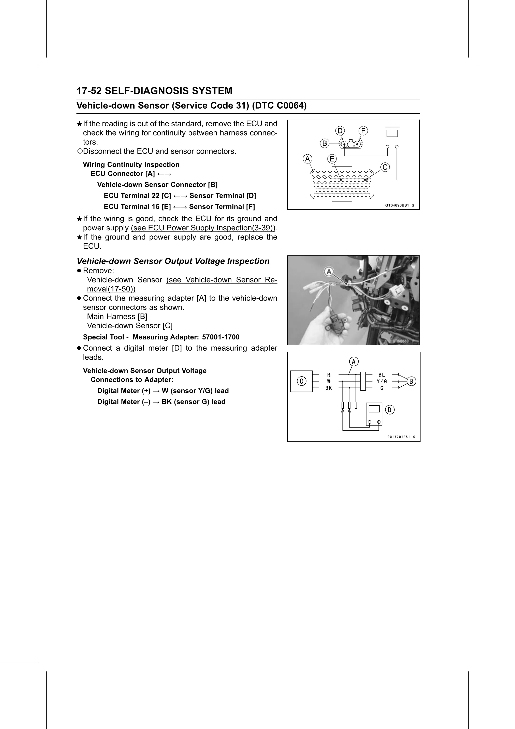
•   Connect the measuring adapter [A] to the vehicle-down
    sensor connectors as shown.
     Main Harness [B]
     Vehicle-down Sensor [C]
    Special Tool - Measuring Adapter: 57001-1700
• Connect
  leads.
          a digital meter [D] to the measuring adapter

    Vehicle-down Sensor Output Voltage
      Connections to Adapter:
        Digital Meter (+) → W (sensor Y/G) lead
        Digital Meter (–) → BK (sensor G) lead