Service Manual (KLZ1000C) — page 678 of 762
Self-Diagnosis System › ETV Actuator Input Voltage Inspection
Text on this page
17-76 SELF-DIAGNOSIS SYSTEM
ETV Actuator (Service Code 58) (DTC P2100)
ETV Actuator Removal
NOTICE
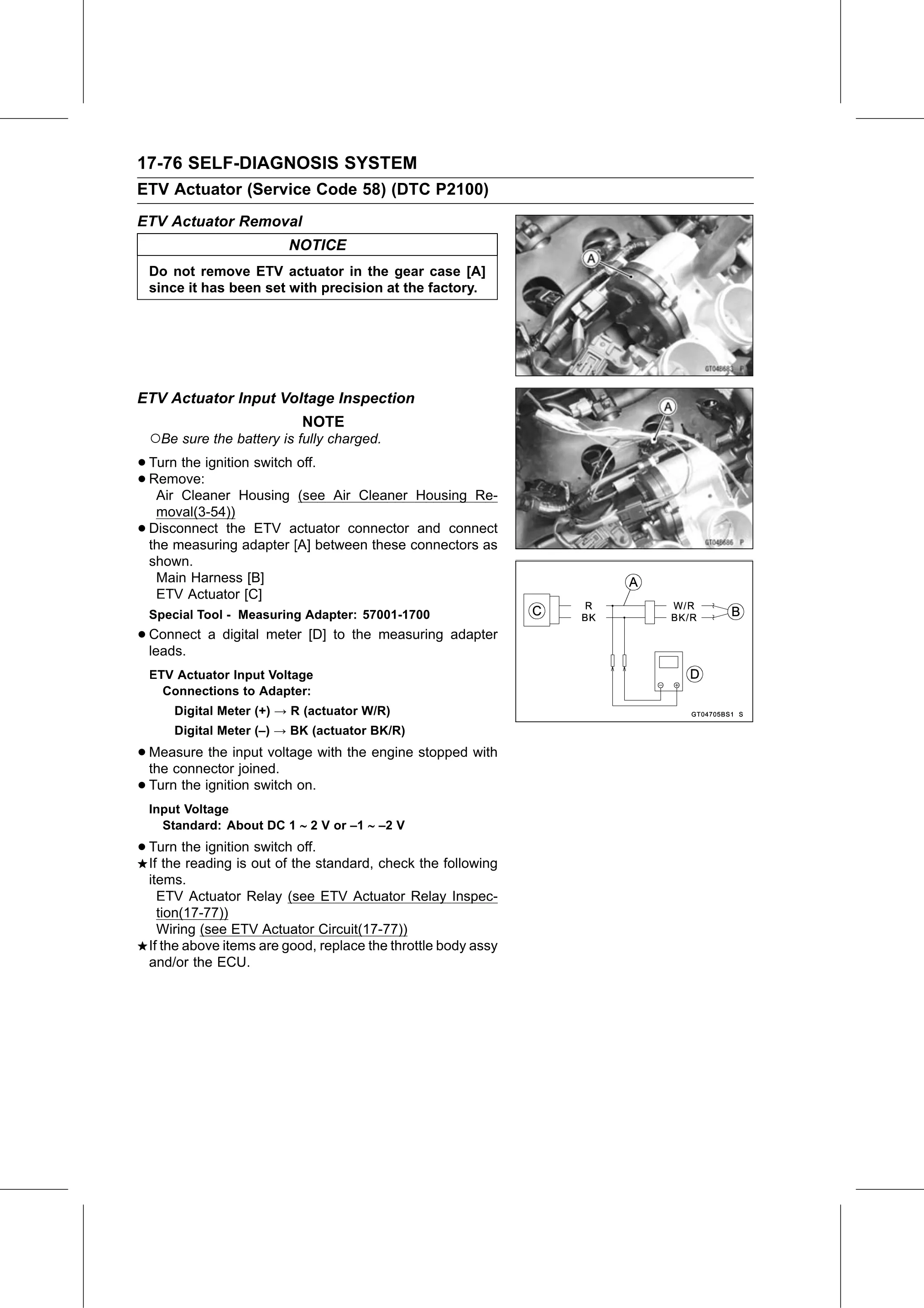
Do not remove ETV actuator in the gear case [A]
since it has been set with precision at the factory.
ETV Actuator Input Voltage Inspection
NOTE
○Be sure the battery is fully charged.
• Turn the ignition switch off.
• Air Cleaner Housing (see Air Cleaner Housing Re-
Remove:
moval(3-54))
• Disconnect the ETV actuator connector and connect
the measuring adapter [A] between these connectors as
shown.
Main Harness [B]
ETV Actuator [C]
Special Tool - Measuring Adapter: 57001-1700
• Connect
leads.
a digital meter [D] to the measuring adapter
ETV Actuator Input Voltage
Connections to Adapter:
Digital Meter (+) → R (actuator W/R)
Digital Meter (–) → BK (actuator BK/R)
• Measure the input voltage with the engine stopped with
the connector joined.
• Turn the ignition switch on.
Input Voltage
Standard: About DC 1 2 V or –1 –2 V
• Turn the ignition switch off.
If the reading is out of the standard, check the following
items.
ETV Actuator Relay (see ETV Actuator Relay Inspec-
tion(17-77))
Wiring (see ETV Actuator Circuit(17-77))
If the above items are good, replace the throttle body assy
and/or the ECU.