Service Manual (KLZ1000C) — page 682 of 762
Self-Diagnosis System › Oxygen Sensor Heater Power Source Voltage Inspection
Text on this page
17-80 SELF-DIAGNOSIS SYSTEM
Oxygen Sensor Heater (Service Code 67) (DTC P0030)
Oxygen Sensor Heater Power Source Voltage
Inspection
                            NOTE
  ○Be sure the battery is fully charged.
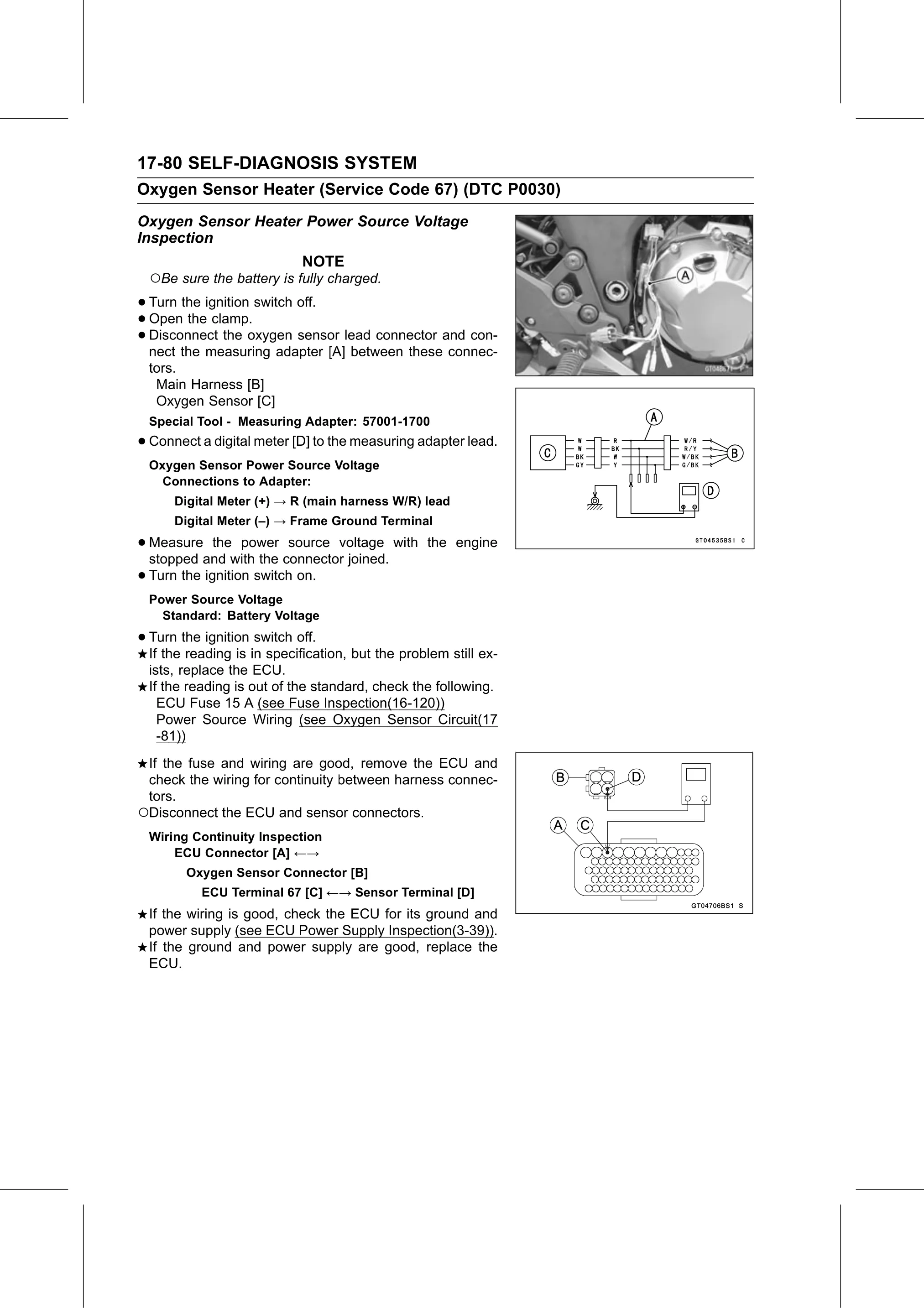
• Turn the ignition switch off.
• Disconnect
  Open  the clamp.
• nect the measuring
              the oxygen sensor lead connector and con-
                       adapter [A] between these connec-
  tors.
   Main Harness [B]
   Oxygen Sensor [C]
  Special Tool - Measuring Adapter: 57001-1700
• Connect a digital meter [D] to the measuring adapter lead.
  Oxygen Sensor Power Source Voltage
    Connections to Adapter:
      Digital Meter (+) → R (main harness W/R) lead
      Digital Meter (–) → Frame Ground Terminal

• Measure    the power source voltage with the engine
  stopped and with the connector joined.
• Turn the ignition switch on.
  Power Source Voltage
    Standard: Battery Voltage

• Turn  the ignition switch off.
  If the reading is in specification, but the problem still ex-
  ists, replace the ECU.
  If the reading is out of the standard, check the following.
    ECU Fuse 15 A (see Fuse Inspection(16-120))
    Power Source Wiring (see Oxygen Sensor Circuit(17
    -81))
 If the fuse and wiring are good, remove the ECU and
 check the wiring for continuity between harness connec-
 tors.
○Disconnect the ECU and sensor connectors.
  Wiring Continuity Inspection
      ECU Connector [A] ←→
        Oxygen Sensor Connector [B]
           ECU Terminal 67 [C] ←→ Sensor Terminal [D]
  If the wiring is good, check the ECU for its ground and
  power supply (see ECU Power Supply Inspection(3-39)).
  If the ground and power supply are good, replace the
  ECU.