Service Manual — page 182 of 715
Fuel System (DFI) › Fuel Injector Output Voltage Inspection
Text on this page
3-92 FUEL SYSTEM (DFI)
Fuel Injectors #1, #2, #3, #4 (Service Code 41, 42, 43, 44) (DTC P0201, P0202,
P0203, P0204)
Fuel Injector Output Voltage Inspection
• Turn the ignition switch off.
•○Remove    the ECU (see ECU Removal).
   Do not disconnect the ECU connector.
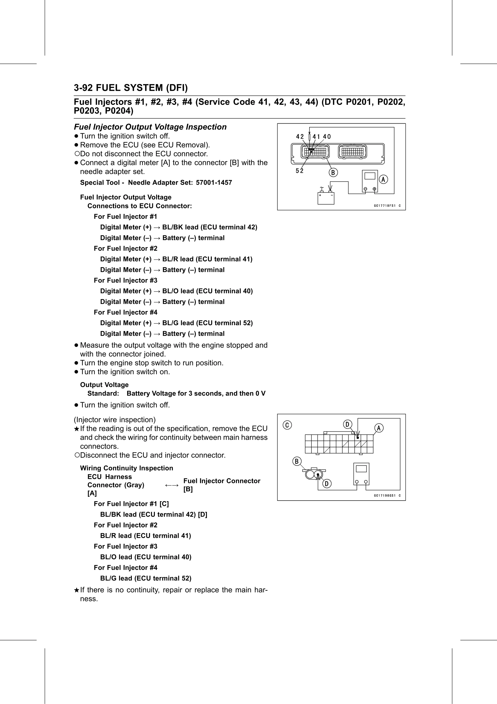
 • Connect  a digital meter [A] to the connector [B] with the
   needle adapter set.
  Special Tool - Needle Adapter Set: 57001-1457

  Fuel Injector Output Voltage
    Connections to ECU Connector:
      For Fuel Injector #1
        Digital Meter (+) → BL/BK lead (ECU terminal 42)
        Digital Meter (–) → Battery (–) terminal
      For Fuel Injector #2
        Digital Meter (+) → BL/R lead (ECU terminal 41)
        Digital Meter (–) → Battery (–) terminal
      For Fuel Injector #3
        Digital Meter (+) → BL/O lead (ECU terminal 40)
        Digital Meter (–) → Battery (–) terminal
      For Fuel Injector #4
        Digital Meter (+) → BL/G lead (ECU terminal 52)
        Digital Meter (–) → Battery (–) terminal

• Measure   the output voltage with the engine stopped and
  with the connector joined.
• Turn  the engine stop switch to run position.
• Turn the ignition switch on.
  Output Voltage
   Standard: Battery Voltage for 3 seconds, and then 0 V

• Turn the ignition switch off.
(Injector wire inspection)
  If the reading is out of the specification, remove the ECU
  and check the wiring for continuity between main harness
  connectors.
○Disconnect the ECU and injector connector.
  Wiring Continuity Inspection
   ECU Harness
                               Fuel Injector Connector
   Connector (Gray)         ←→
                               [B]
   [A]
      For Fuel Injector #1 [C]
        BL/BK lead (ECU terminal 42) [D]
      For Fuel Injector #2
        BL/R lead (ECU terminal 41)
      For Fuel Injector #3
        BL/O lead (ECU terminal 40)
      For Fuel Injector #4
        BL/G lead (ECU terminal 52)
  If there is no continuity, repair or replace the main har-
  ness.