Service Manual — page 474 of 715
Brakes › ABS Hydraulic Unit Inspection
Text on this page
12-52 BRAKES
Anti-Lock Brake System
                          NOTICE
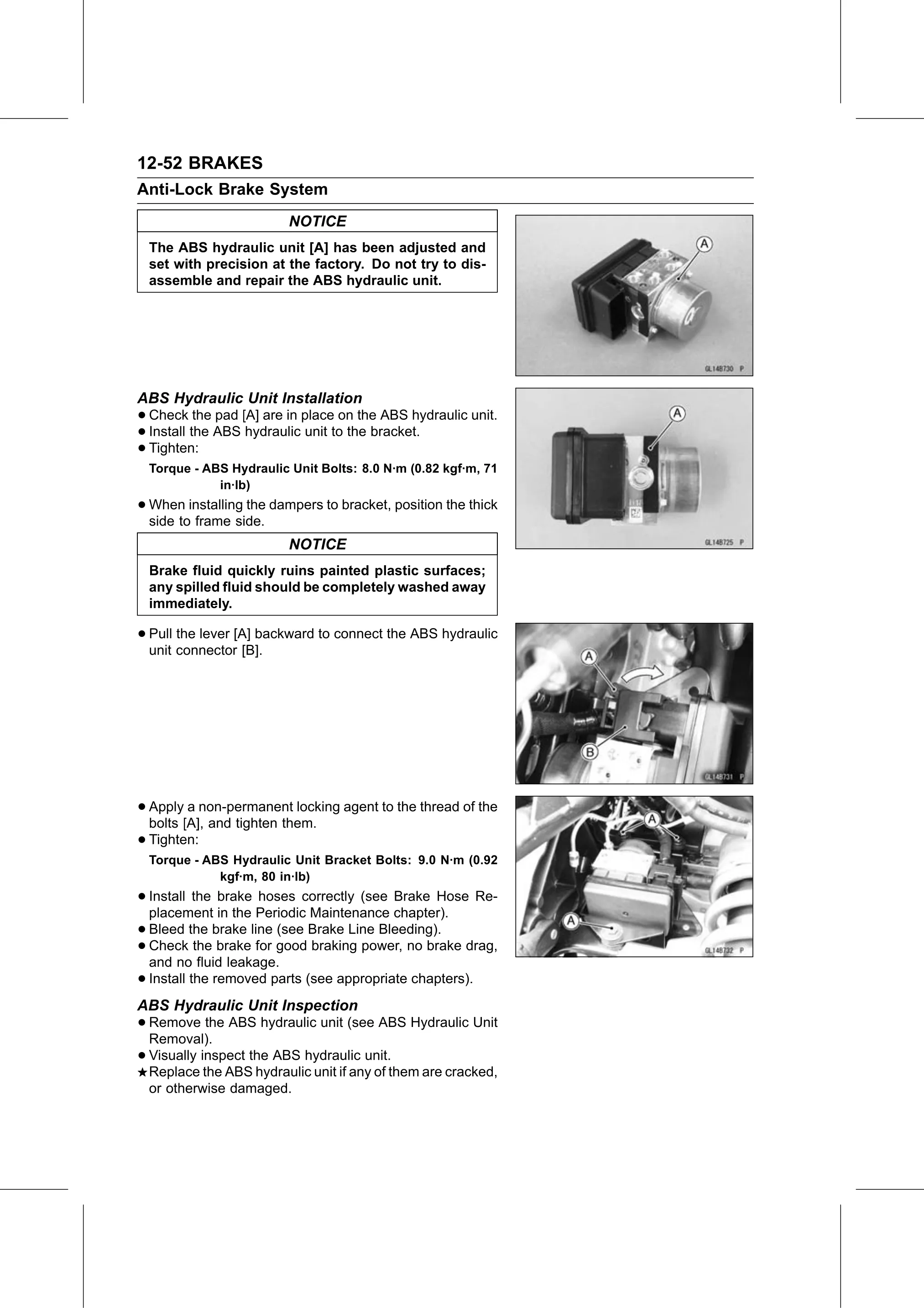
  The ABS hydraulic unit [A] has been adjusted and
  set with precision at the factory. Do not try to dis-
  assemble and repair the ABS hydraulic unit.

ABS Hydraulic Unit Installation
• Check    the pad [A] are in place on the ABS hydraulic unit.
• Install the ABS hydraulic unit to the bracket.
• Tighten:
  Torque - ABS Hydraulic Unit Bolts: 8.0 N·m (0.82 kgf·m, 71
             in·lb)
• When   installing the dampers to bracket, position the thick
  side to frame side.
                          NOTICE
  Brake fluid quickly ruins painted plastic surfaces;
  any spilled fluid should be completely washed away
  immediately.

• Pull the lever [A] backward to connect the ABS hydraulic
  unit connector [B].

• Apply  a non-permanent locking agent to the thread of the
  bolts [A], and tighten them.
• Tighten:
  Torque - ABS Hydraulic Unit Bracket Bolts: 9.0 N·m (0.92
             kgf·m, 80 in·lb)
• Install  the brake hoses correctly (see Brake Hose Re-
  placement in the Periodic Maintenance chapter).
• Bleed   the brake line (see Brake Line Bleeding).
• and nothe
  Check         brake for good braking power, no brake drag,
            fluid leakage.
• Install the removed parts (see appropriate chapters).
ABS Hydraulic Unit Inspection
• Remove
  Removal).
            the ABS hydraulic unit (see ABS Hydraulic Unit

• Visually inspect the ABS hydraulic unit.
  Replace the ABS hydraulic unit if any of them are cracked,
  or otherwise damaged.