Service Manual — page 476 of 715
Brakes › Rear Wheel Rotation Sensor Installation
Text on this page
12-54 BRAKES
Anti-Lock Brake System
Rear Wheel Rotation Sensor Removal
                          NOTICE
    The wheel rotation sensor should be handled care-
    fully, never struck sharply, as with a hammer, or al-
    lowed to fall on a hard surface since the wheel rota-
    tion sensor is precision made. Be careful not to get
    water or mud on the wheel rotation sensor.
    Do not try to disassemble or repair the wheel rota-
    tion sensor.

• Remove:
   Fuel Tank (see Fuel Tank Removal in the Fuel System
     (DFI) chapter)
•   Turn up the heat insulation rubber plate.
•   Disconnect the rear wheel rotation sensor lead connector
    [A].
•   Clear the sensor lead from the clamps [B].

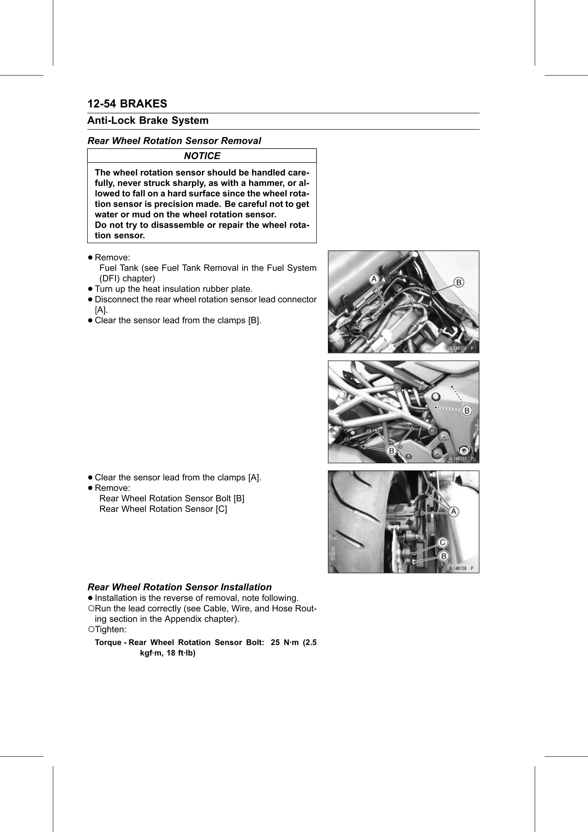
• Clear the sensor lead from the clamps [A].
• Remove:
   Rear Wheel Rotation Sensor Bolt [B]
     Rear Wheel Rotation Sensor [C]

Rear Wheel Rotation Sensor Installation
•○Installation is the reverse of removal, note following.
  Run the lead correctly (see Cable, Wire, and Hose Rout-
 ing section in the Appendix chapter).
○Tighten:
    Torque - Rear Wheel Rotation Sensor Bolt: 25 N·m (2.5
               kgf·m, 18 ft·lb)