Service Manual — page 593 of 715
Electrical System › Alternator Rotor Installation
Text on this page
ELECTRICAL SYSTEM 16-33
Charging System

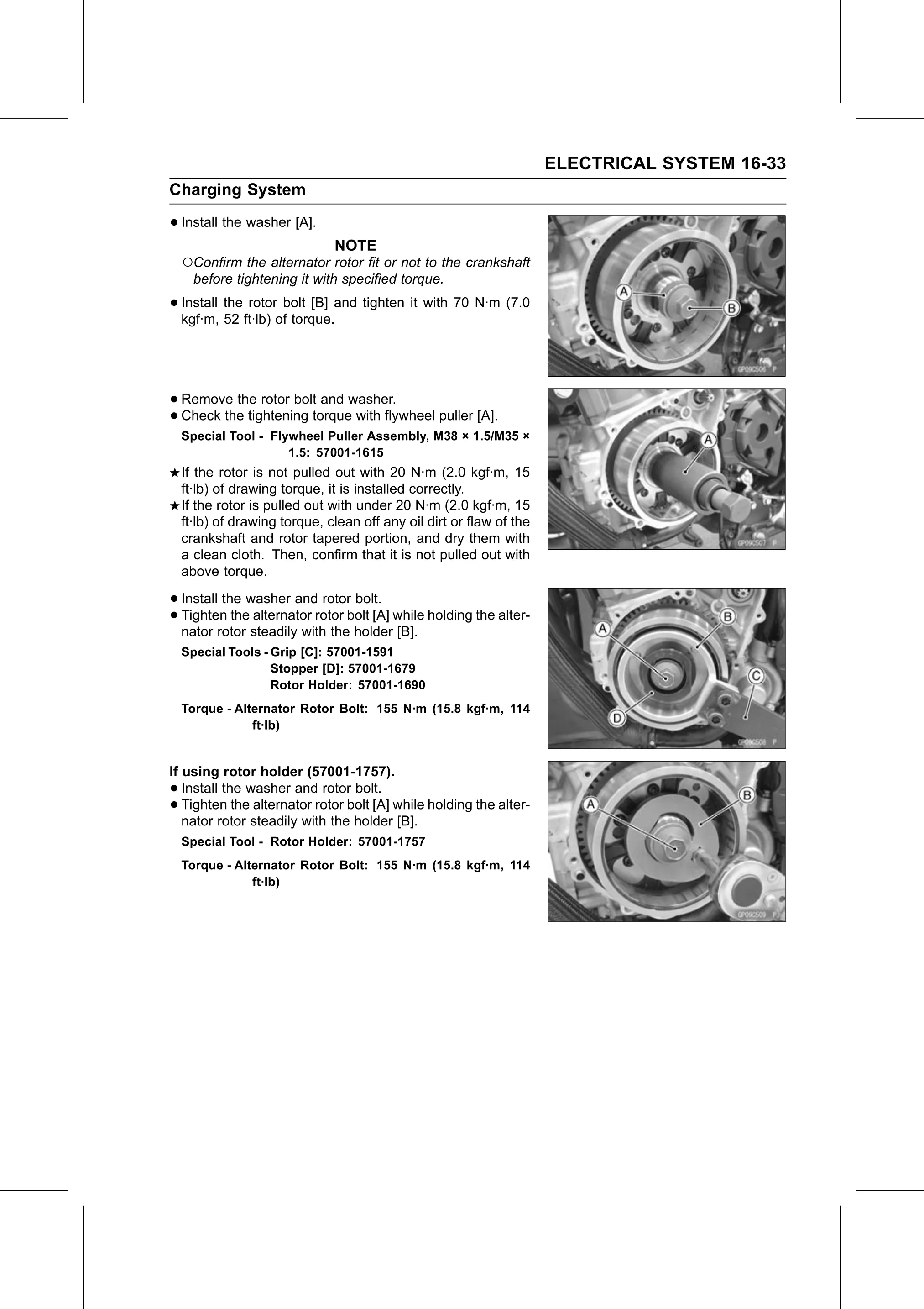
• Install the washer [A].
                               NOTE
    ○Confirm the alternator rotor fit or not to the crankshaft
      before tightening it with specified torque.

• Install the rotor bolt [B] and tighten it with 70 N·m (7.0
  kgf·m, 52 ft·lb) of torque.

• Remove  the rotor bolt and washer.
• Check the tightening torque with flywheel puller [A].
    Special Tool - Flywheel Puller Assembly, M38 × 1.5/M35 ×
                      1.5: 57001-1615
    If the rotor is not pulled out with 20 N·m (2.0 kgf·m, 15
    ft·lb) of drawing torque, it is installed correctly.
    If the rotor is pulled out with under 20 N·m (2.0 kgf·m, 15
    ft·lb) of drawing torque, clean off any oil dirt or flaw of the
    crankshaft and rotor tapered portion, and dry them with
    a clean cloth. Then, confirm that it is not pulled out with
    above torque.

• Install the washer and rotor bolt.
• Tighten   the alternator rotor bolt [A] while holding the alter-
  nator rotor steadily with the holder [B].
    Special Tools - Grip [C]: 57001-1591
                    Stopper [D]: 57001-1679
                    Rotor Holder: 57001-1690
    Torque - Alternator Rotor Bolt: 155 N·m (15.8 kgf·m, 114
                ft·lb)

If using rotor holder (57001-1757).
•  Install the washer and rotor bolt.
•  Tighten the alternator rotor bolt [A] while holding the alter-
   nator rotor steadily with the holder [B].
    Special Tool - Rotor Holder: 57001-1757
    Torque - Alternator Rotor Bolt: 155 N·m (15.8 kgf·m, 114
                ft·lb)