Service Manual (KLZ1000C) — page 124 of 762
Fuel System (DFI) › ECU Power Supply Inspection
Text on this page
3-40 FUEL SYSTEM (DFI)
ECU
    If the wiring is good, check the power source voltage of
    the ECU.
                              NOTE
    ○Be sure the battery is fully charged.
• Connect the ECU connector.
• Left Inner Middle Fairing (see Inner Middle Fairing Re-
  Remove:

     moval(15-15))
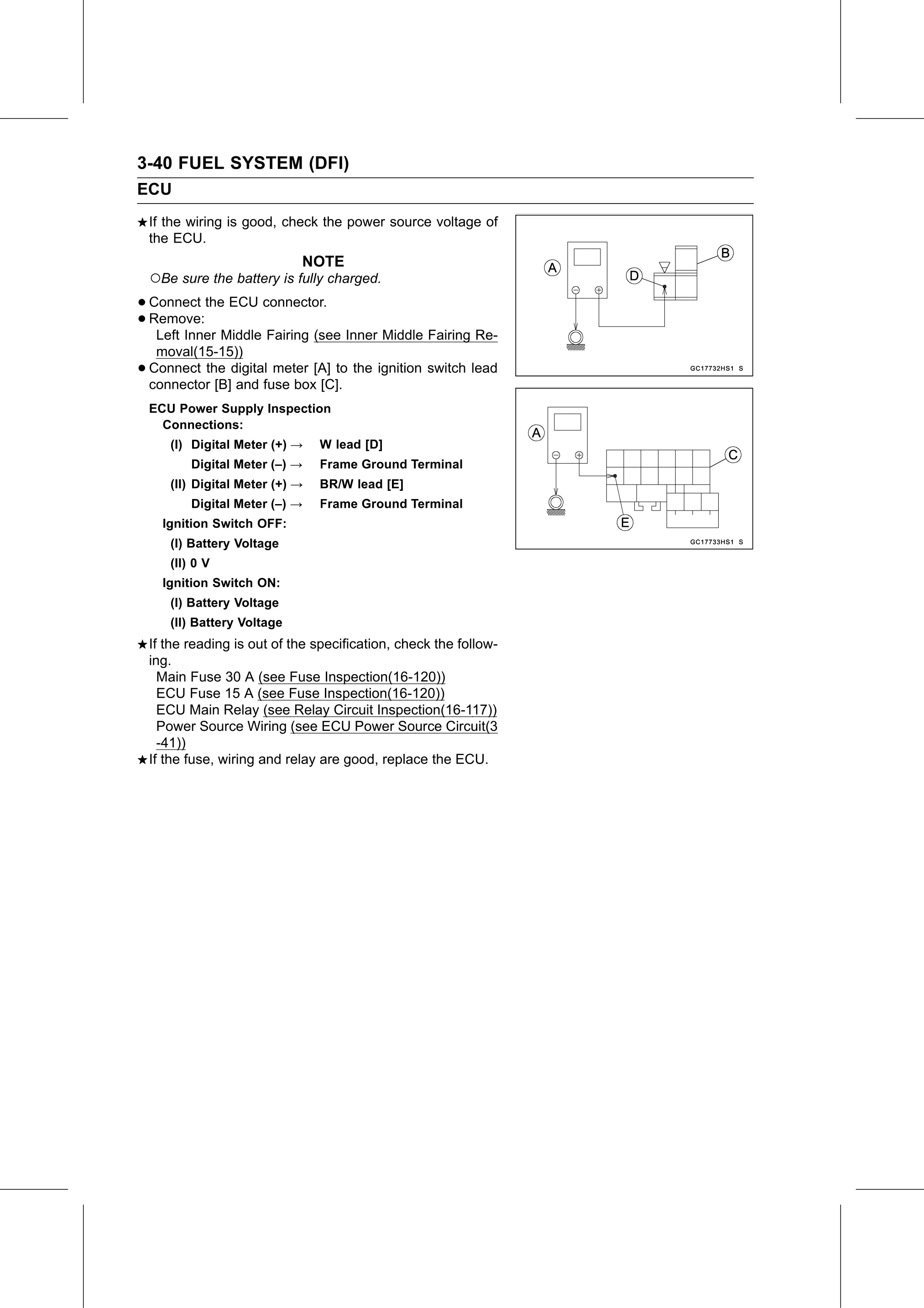
•   Connect the digital meter [A] to the ignition switch lead
    connector [B] and fuse box [C].
    ECU Power Supply Inspection
      Connections:
       (I) Digital Meter (+) →    W lead [D]
           Digital Meter (–) →    Frame Ground Terminal
       (II) Digital Meter (+) →   BR/W lead [E]
           Digital Meter (–) →    Frame Ground Terminal
      Ignition Switch OFF:
       (I) Battery Voltage
       (II) 0 V
      Ignition Switch ON:
       (I) Battery Voltage
       (II) Battery Voltage
    If the reading is out of the specification, check the follow-
    ing.
      Main Fuse 30 A (see Fuse Inspection(16-120))
      ECU Fuse 15 A (see Fuse Inspection(16-120))
      ECU Main Relay (see Relay Circuit Inspection(16-117))
      Power Source Wiring (see ECU Power Source Circuit(3
      -41))
    If the fuse, wiring and relay are good, replace the ECU.