Service Manual (KLZ1000C) — page 527 of 762
Electrical System › Crankshaft Sensor Peak Voltage Inspection
Text on this page
ELECTRICAL SYSTEM 16-45
Ignition System
Crankshaft Sensor Inspection
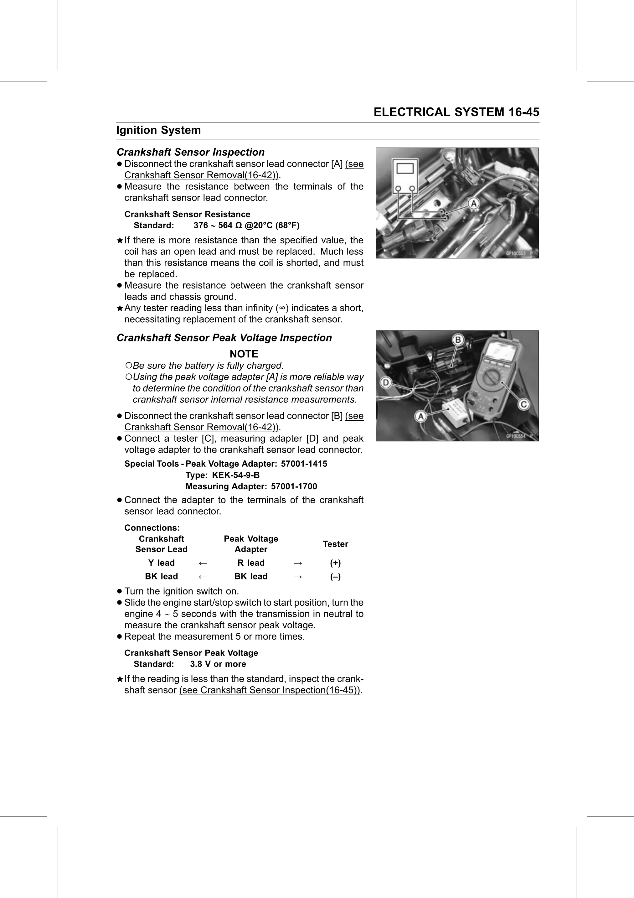
• Disconnect the crankshaft sensor lead connector [A] (see
Crankshaft Sensor Removal(16-42)).
• Measure the resistance between the terminals of the
crankshaft sensor lead connector.
Crankshaft Sensor Resistance
Standard: 376 564 Ω @20°C (68°F)
If there is more resistance than the specified value, the
coil has an open lead and must be replaced. Much less
than this resistance means the coil is shorted, and must
be replaced.
• Measure the resistance between the crankshaft sensor
leads and chassis ground.
Any tester reading less than infinity (∞) indicates a short,
necessitating replacement of the crankshaft sensor.
Crankshaft Sensor Peak Voltage Inspection
NOTE
○Be sure the battery is fully charged.
○Using the peak voltage adapter [A] is more reliable way
to determine the condition of the crankshaft sensor than
crankshaft sensor internal resistance measurements.
• Disconnect the crankshaft sensor lead connector [B] (see
Crankshaft Sensor Removal(16-42)).
• Connect a tester [C], measuring adapter [D] and peak
voltage adapter to the crankshaft sensor lead connector.
Special Tools - Peak Voltage Adapter: 57001-1415
Type: KEK-54-9-B
Measuring Adapter: 57001-1700
• Connect the adapter to the terminals of the crankshaft
sensor lead connector.
Connections:
Crankshaft Peak Voltage
Tester
Sensor Lead Adapter
Y lead ← R lead → (+)
BK lead ← BK lead → (–)
• Turn the ignition switch on.
• Slide the engine start/stop switch to start position, turn the
engine 4 5 seconds with the transmission in neutral to
measure the crankshaft sensor peak voltage.
• Repeat the measurement 5 or more times.
Crankshaft Sensor Peak Voltage
Standard: 3.8 V or more
If the reading is less than the standard, inspect the crank-
shaft sensor (see Crankshaft Sensor Inspection(16-45)).