Service Manual (KLZ1000C) — page 600 of 762
Electrical System › Diode Circuit Inspection
Text on this page
16-118 ELECTRICAL SYSTEM
Relay Box
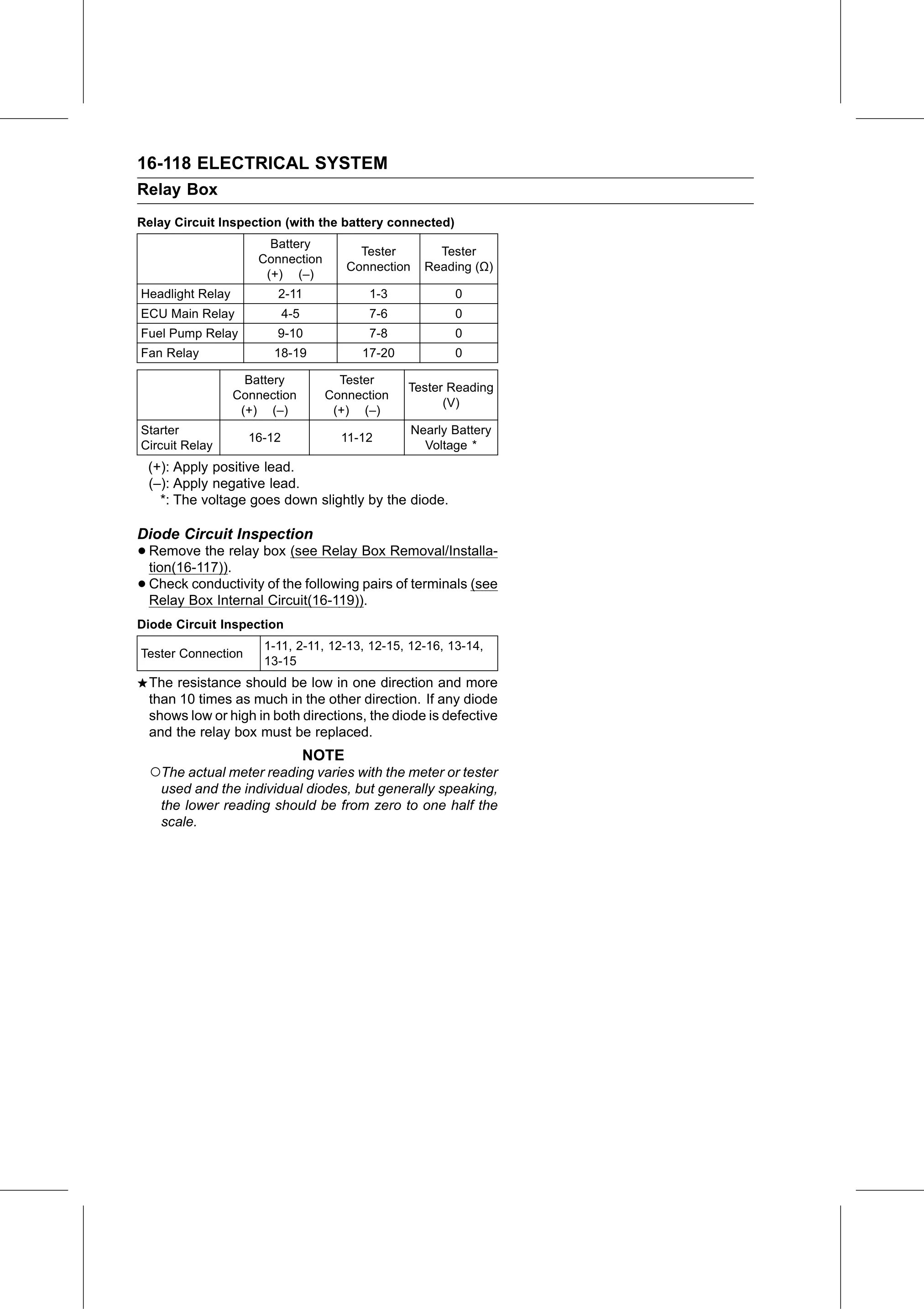
Relay Circuit Inspection (with the battery connected)
                        Battery
                                           Tester         Tester
                      Connection
                                         Connection     Reading (Ω)
                       (+) (–)
Headlight Relay          2-11               1-3              0
ECU Main Relay              4-5             7-6              0
Fuel Pump Relay          9-10               7-8              0
Fan Relay               18-19              17-20             0

                    Battery           Tester
                                                   Tester Reading
                  Connection        Connection
                                                         (V)
                   (+) (–)           (+) (–)
Starter                                               Nearly Battery
                    16-12             11-12
Circuit Relay                                           Voltage *
 (+): Apply positive lead.
 (–): Apply negative lead.
   *: The voltage goes down slightly by the diode.

Diode Circuit Inspection
• Remove   the relay box (see Relay Box Removal/Installa-
  tion(16-117)).
• Check  conductivity of the following pairs of terminals (see
  Relay Box Internal Circuit(16-119)).
Diode Circuit Inspection
                      1-11, 2-11, 12-13, 12-15, 12-16, 13-14,
Tester Connection
                      13-15
  The resistance should be low in one direction and more
  than 10 times as much in the other direction. If any diode
  shows low or high in both directions, the diode is defective
  and the relay box must be replaced.
                                  NOTE
  ○The actual meter reading varies with the meter or tester
    used and the individual diodes, but generally speaking,
    the lower reading should be from zero to one half the
    scale.