Service Manual — page 279 of 715
Engine Top End › Cylinder Head Warp Inspection
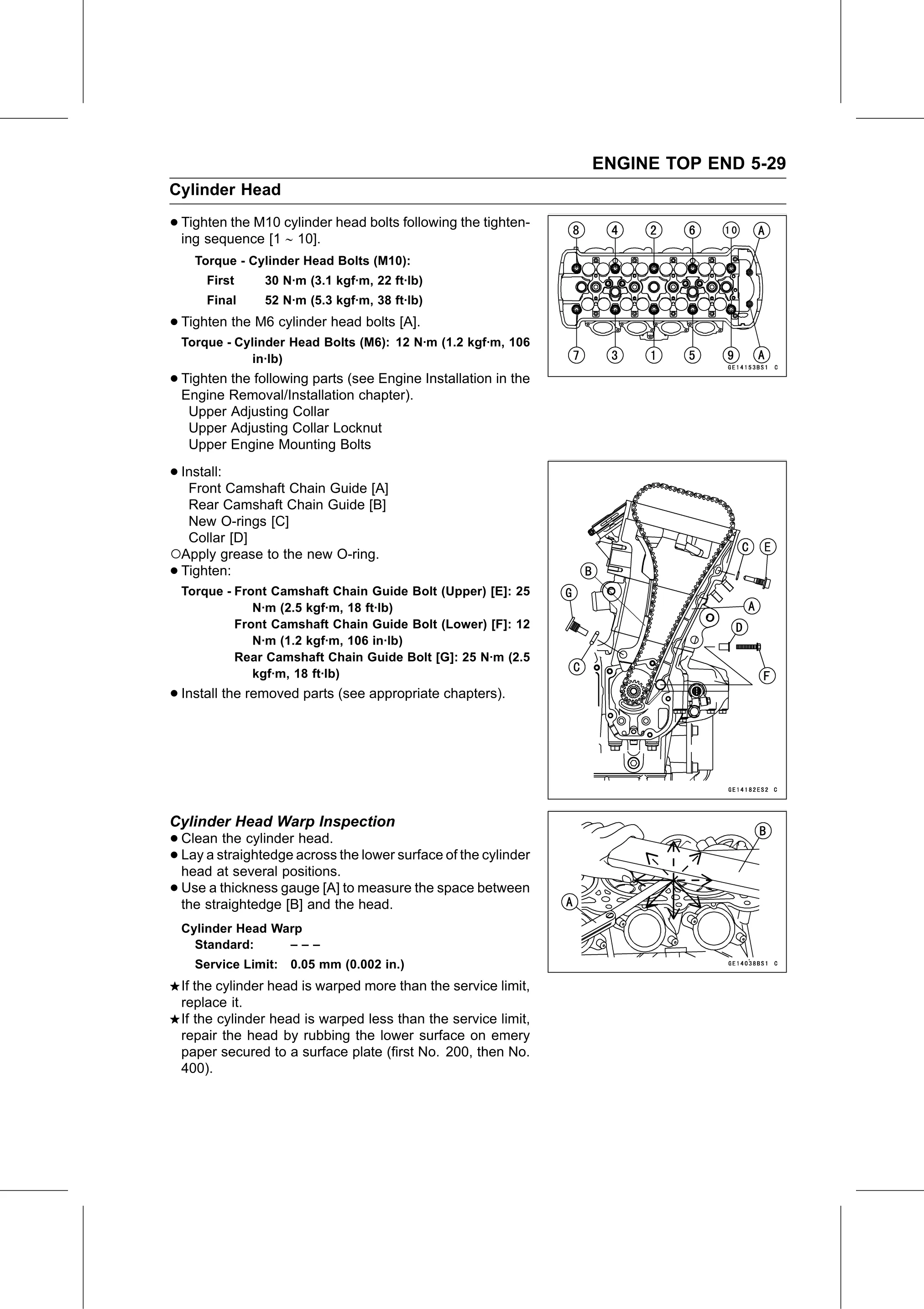
Text on this page
ENGINE TOP END 5-29
Cylinder Head

• Tighten the M10 cylinder head bolts following the tighten-
  ing sequence [1 ∼ 10].
      Torque - Cylinder Head Bolts (M10):
        First     30 N·m (3.1 kgf·m, 22 ft·lb)
        Final     52 N·m (5.3 kgf·m, 38 ft·lb)

• Tighten the M6 cylinder head bolts [A].
    Torque - Cylinder Head Bolts (M6): 12 N·m (1.2 kgf·m, 106
                in·lb)
• Tighten the following parts (see Engine Installation in the
  Engine Removal/Installation chapter).
     Upper Adjusting Collar
     Upper Adjusting Collar Locknut
     Upper Engine Mounting Bolts

• Install:
   Front Camshaft Chain Guide [A]
  Rear Camshaft Chain Guide [B]
  New O-rings [C]
  Collar [D]
○Apply grease to the new O-ring.
•Tighten:
    Torque - Front Camshaft Chain Guide Bolt (Upper) [E]: 25
                N·m (2.5 kgf·m, 18 ft·lb)
             Front Camshaft Chain Guide Bolt (Lower) [F]: 12
                N·m (1.2 kgf·m, 106 in·lb)
             Rear Camshaft Chain Guide Bolt [G]: 25 N·m (2.5
                kgf·m, 18 ft·lb)
• Install the removed parts (see appropriate chapters).

Cylinder Head Warp Inspection
• Clean   the cylinder head.
• head at several positions.
  Lay a straightedge  across the lower surface of the cylinder

• Use  a thickness gauge [A] to measure the space between
  the straightedge [B] and the head.
    Cylinder Head Warp
      Standard:     –––
      Service Limit:   0.05 mm (0.002 in.)
    If the cylinder head is warped more than the service limit,
    replace it.
    If the cylinder head is warped less than the service limit,
    repair the head by rubbing the lower surface on emery
    paper secured to a surface plate (first No. 200, then No.
    400).