Service Manual — page 552 of 715
Frame › Flap and Rear Fender Installation
Text on this page
15-24 FRAME
Fenders

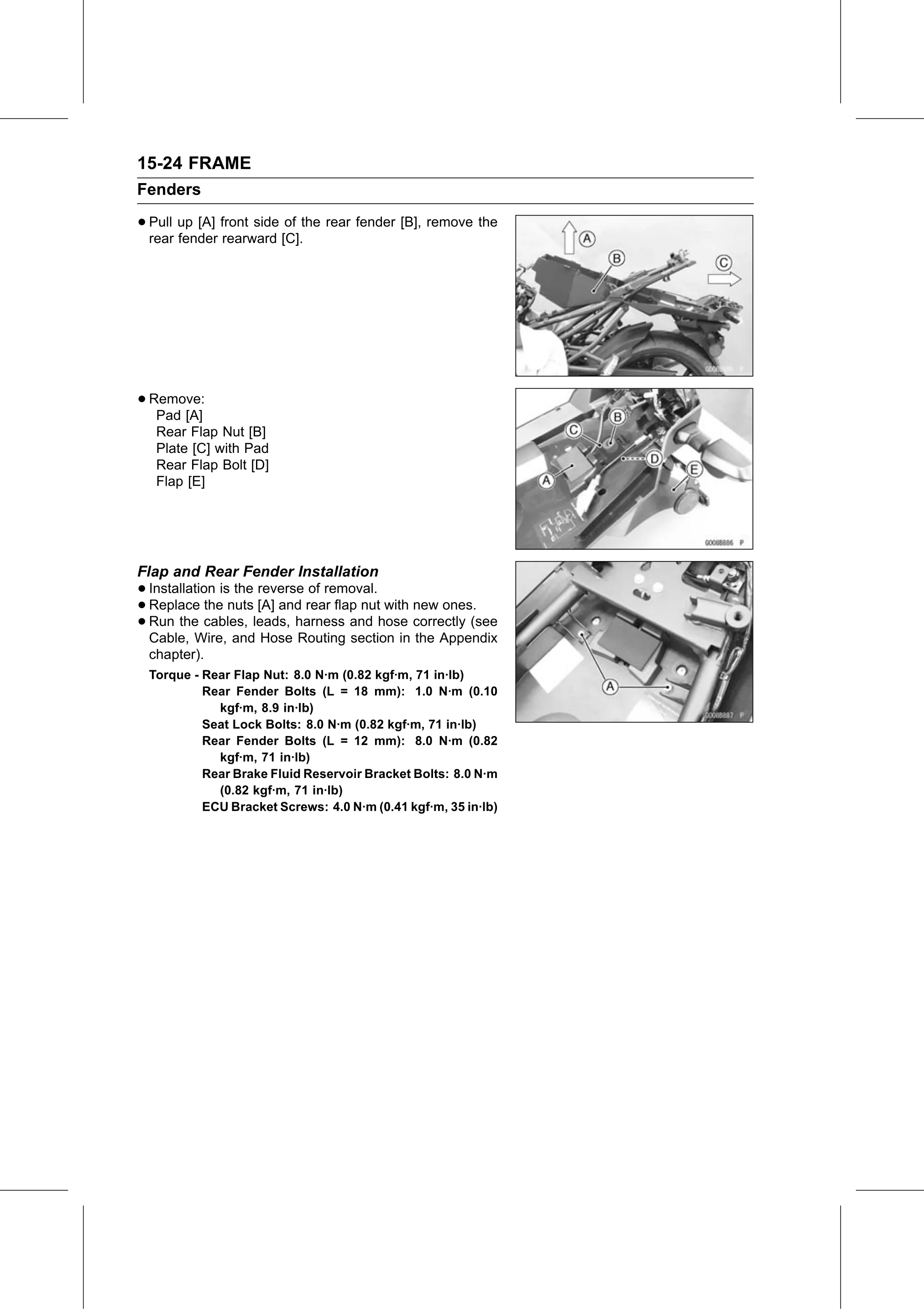
• Pull up [A] front side of the rear fender [B], remove the
  rear fender rearward [C].

• Remove:
   Pad [A]
   Rear Flap Nut [B]
   Plate [C] with Pad
   Rear Flap Bolt [D]
   Flap [E]

Flap and Rear Fender Installation
• Installation  is the reverse of removal.
• Replace    the nuts [A] and rear flap nut with new ones.
• Cable, Wire, andleads,
  Run  the  cables,          harness and hose correctly (see
                        Hose Routing section in the Appendix
 chapter).
 Torque - Rear Flap Nut: 8.0 N·m (0.82 kgf·m, 71 in·lb)
          Rear Fender Bolts (L = 18 mm): 1.0 N·m (0.10
            kgf·m, 8.9 in·lb)
          Seat Lock Bolts: 8.0 N·m (0.82 kgf·m, 71 in·lb)
          Rear Fender Bolts (L = 12 mm): 8.0 N·m (0.82
            kgf·m, 71 in·lb)
          Rear Brake Fluid Reservoir Bracket Bolts: 8.0 N·m
            (0.82 kgf·m, 71 in·lb)
          ECU Bracket Screws: 4.0 N·m (0.41 kgf·m, 35 in·lb)