Service Manual — page 642 of 715
Electrical System › Meter Unit Inspection
Text on this page
16-82 ELECTRICAL SYSTEM
Meter, Gauge, Indicator Unit
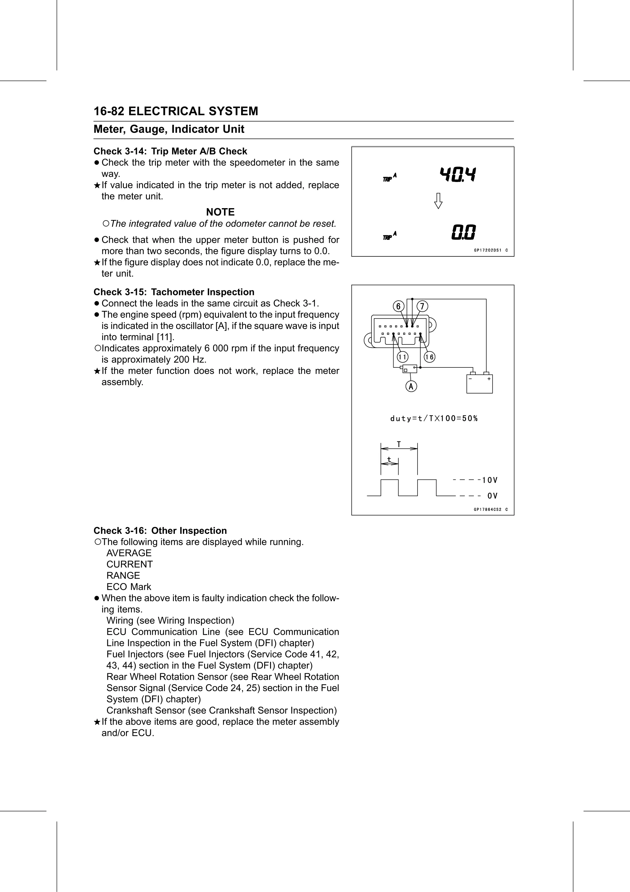
Check 3-14: Trip Meter A/B Check
•Check the trip meter with the speedometer in the same
 way.
 If value indicated in the trip meter is not added, replace
 the meter unit.
                              NOTE
    ○The integrated value of the odometer cannot be reset.
• Check  that when the upper meter button is pushed for
  more than two seconds, the figure display turns to 0.0.
    If the figure display does not indicate 0.0, replace the me-
    ter unit.
Check 3-15: Tachometer Inspection
•Connect the leads in the same circuit as Check 3-1.
•The engine speed (rpm) equivalent to the input frequency
 is indicated in the oscillator [A], if the square wave is input
 into terminal [11].
○Indicates approximately 6 000 rpm if the input frequency
 is approximately 200 Hz.
 If the meter function does not work, replace the meter
 assembly.

Check 3-16: Other Inspection
○The following items are displayed while running.
   AVERAGE
   CURRENT
   RANGE
   ECO Mark
•When the above item is faulty indication check the follow-
 ing items.
   Wiring (see Wiring Inspection)
   ECU Communication Line (see ECU Communication
   Line Inspection in the Fuel System (DFI) chapter)
   Fuel Injectors (see Fuel Injectors (Service Code 41, 42,
   43, 44) section in the Fuel System (DFI) chapter)
   Rear Wheel Rotation Sensor (see Rear Wheel Rotation
   Sensor Signal (Service Code 24, 25) section in the Fuel
   System (DFI) chapter)
   Crankshaft Sensor (see Crankshaft Sensor Inspection)
 If the above items are good, replace the meter assembly
 and/or ECU.