Service Manual — page 641 of 715
Electrical System › Meter Unit Inspection
Text on this page
ELECTRICAL SYSTEM 16-81
Meter, Gauge, Indicator Unit

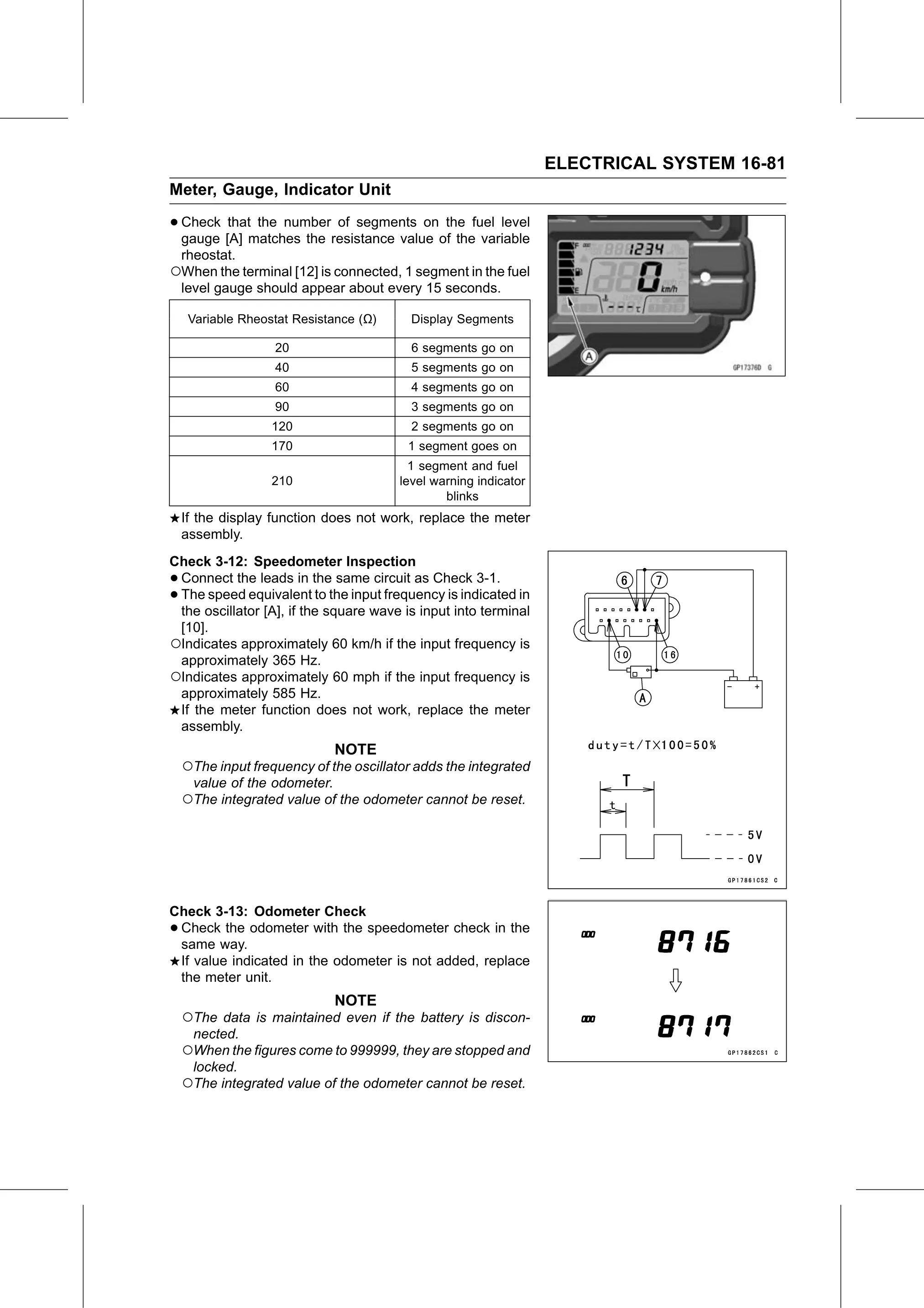
• Check  that the number of segments on the fuel level
  gauge [A] matches the resistance value of the variable
    rheostat.
○When the terminal [12] is connected, 1 segment in the fuel
    level gauge should appear about every 15 seconds.

     Variable Rheostat Resistance (Ω)     Display Segments

                   20                     6 segments go on
                   40                     5 segments go on
                   60                     4 segments go on
                   90                     3 segments go on
                   120                    2 segments go on
                   170                   1 segment goes on
                                          1 segment and fuel
                   210                  level warning indicator
                                                blinks
    If the display function does not work, replace the meter
    assembly.
Check 3-12: Speedometer Inspection
•Connect the leads in the same circuit as Check 3-1.
•The speed equivalent to the input frequency is indicated in
 the oscillator [A], if the square wave is input into terminal
 [10].
○Indicates approximately 60 km/h if the input frequency is
 approximately 365 Hz.
○Indicates approximately 60 mph if the input frequency is
 approximately 585 Hz.
 If the meter function does not work, replace the meter
 assembly.
                              NOTE
    ○The input frequency of the oscillator adds the integrated
     value of the odometer.
    ○The integrated value of the odometer cannot be reset.

Check 3-13: Odometer Check
•Check the odometer with the speedometer check in the
 same way.
 If value indicated in the odometer is not added, replace
 the meter unit.
                              NOTE
    ○The data is maintained even if the battery is discon-
     nected.
    ○When the figures come to 999999, they are stopped and
     locked.
    ○The integrated value of the odometer cannot be reset.