Service Manual — page 633 of 715
Electrical System › Meter System Inspection
Text on this page
ELECTRICAL SYSTEM 16-73
Meter, Gauge, Indicator Unit
Meter System Inspection
Check 2-1: Outside Temperature Inspection
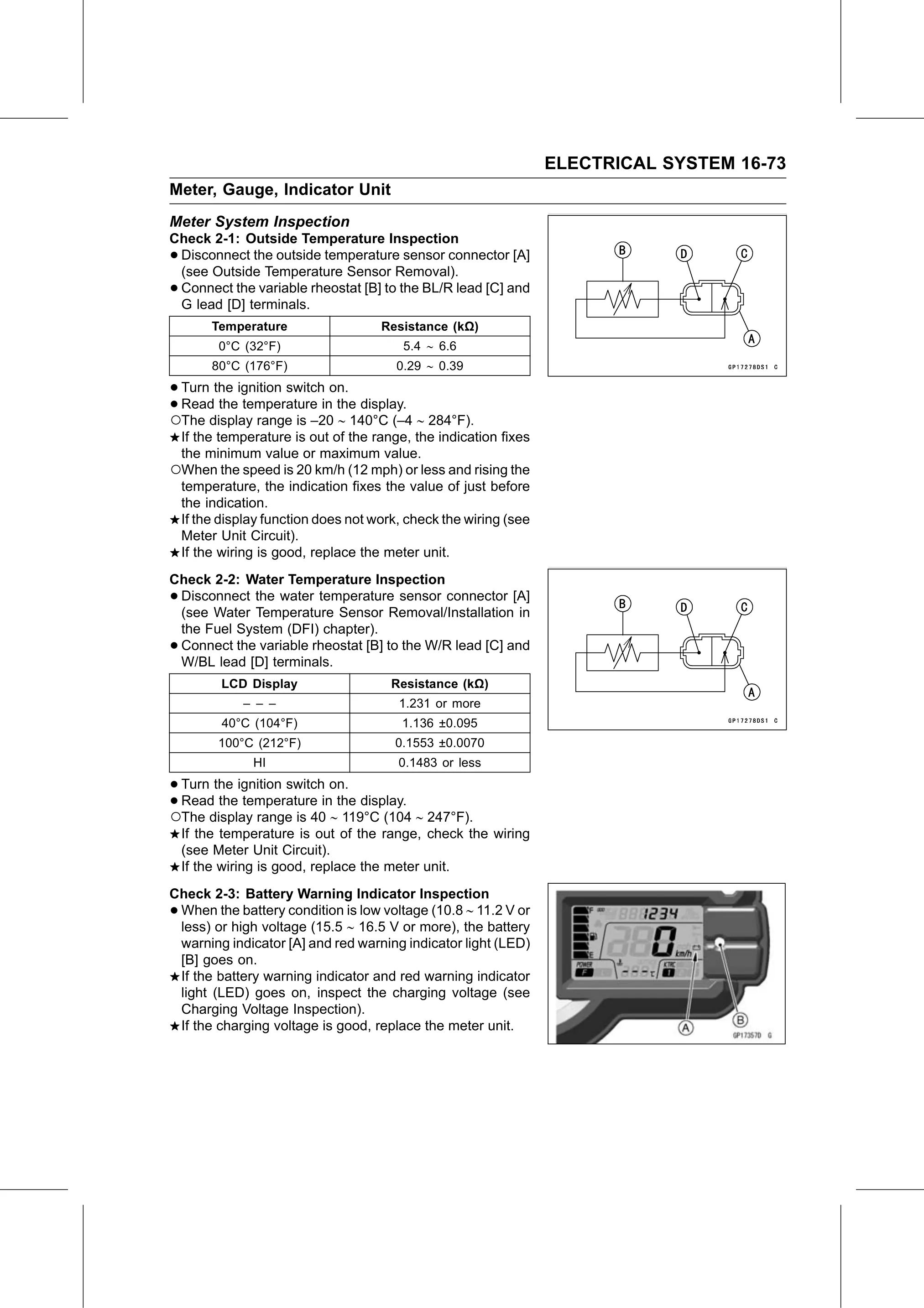
•Disconnect the outside temperature sensor connector [A]
 (see Outside Temperature Sensor Removal).
•Connect the variable rheostat [B] to the BL/R lead [C] and
 G lead [D] terminals.
        Temperature                 Resistance (kΩ)
          0°C (32°F)                   5.4 ∼ 6.6
        80°C (176°F)                  0.29 ∼ 0.39

• Turn the ignition switch on.
•○The display
  Read  the temperature in the display.
              range is –20 ∼ 140°C (–4 ∼ 284°F).
 If the temperature is out of the range, the indication fixes
 the minimum value or maximum value.
○When the speed is 20 km/h (12 mph) or less and rising the
 temperature, the indication fixes the value of just before
 the indication.
 If the display function does not work, check the wiring (see
 Meter Unit Circuit).
 If the wiring is good, replace the meter unit.
Check 2-2: Water Temperature Inspection
•Disconnect the water temperature sensor connector [A]
 (see Water Temperature Sensor Removal/Installation in
 the Fuel System (DFI) chapter).
•Connect the variable rheostat [B] to the W/R lead [C] and
 W/BL lead [D] terminals.
          LCD Display                Resistance (kΩ)
             – – –                    1.231 or more
          40°C (104°F)                 1.136 ±0.095
         100°C (212°F)                0.1553 ±0.0070
               HI                     0.1483 or less

• Turn the ignition switch on.
•○The display
  Read  the temperature in the display.
              range is 40 ∼ 119°C (104 ∼ 247°F).
    If the temperature is out of the range, check the wiring
    (see Meter Unit Circuit).
    If the wiring is good, replace the meter unit.
Check 2-3: Battery Warning Indicator Inspection
•When the battery condition is low voltage (10.8 ∼ 11.2 V or
 less) or high voltage (15.5 ∼ 16.5 V or more), the battery
 warning indicator [A] and red warning indicator light (LED)
 [B] goes on.
 If the battery warning indicator and red warning indicator
 light (LED) goes on, inspect the charging voltage (see
 Charging Voltage Inspection).
 If the charging voltage is good, replace the meter unit.