Service Manual — page 635 of 715
Electrical System › Meter Unit Inspection
Text on this page
ELECTRICAL SYSTEM 16-75
Meter, Gauge, Indicator Unit

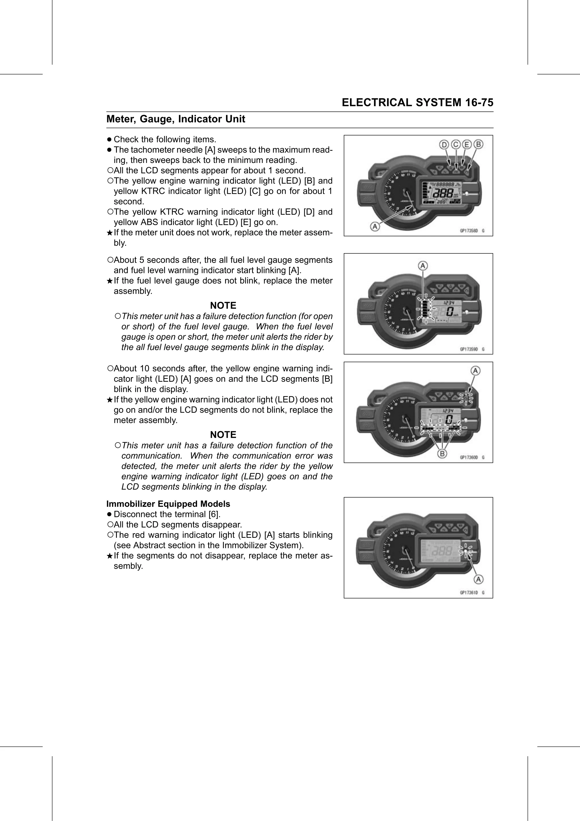
• Check   the following items.
• ing, then sweepsneedle
  The  tachometer          [A] sweeps to the maximum read-
                     back to the minimum reading.
○All the LCD segments appear for about 1 second.
○The yellow engine warning indicator light (LED) [B] and
 yellow KTRC indicator light (LED) [C] go on for about 1
 second.
○The yellow KTRC warning indicator light (LED) [D] and
 yellow ABS indicator light (LED) [E] go on.
 If the meter unit does not work, replace the meter assem-
 bly.

○About 5 seconds after, the all fuel level gauge segments
    and fuel level warning indicator start blinking [A].
    If the fuel level gauge does not blink, replace the meter
    assembly.
                              NOTE
    ○This meter unit has a failure detection function (for open
      or short) of the fuel level gauge. When the fuel level
      gauge is open or short, the meter unit alerts the rider by
      the all fuel level gauge segments blink in the display.

○About 10 seconds after, the yellow engine warning indi-
    cator light (LED) [A] goes on and the LCD segments [B]
    blink in the display.
    If the yellow engine warning indicator light (LED) does not
    go on and/or the LCD segments do not blink, replace the
    meter assembly.
                              NOTE
    ○This meter unit has a failure detection function of the
     communication. When the communication error was
     detected, the meter unit alerts the rider by the yellow
     engine warning indicator light (LED) goes on and the
     LCD segments blinking in the display.
Immobilizer Equipped Models
• Disconnect the terminal [6].
○All the LCD segments disappear.
○The red warning indicator light (LED) [A] starts blinking
  (see Abstract section in the Immobilizer System).
  If the segments do not disappear, replace the meter as-
  sembly.